この記事では書籍「世界一美しい錯視アート」に掲載されている「アヒルのおしゃべり」という作品をProcessingを使って再現してみます。
アヒルのおしゃべり
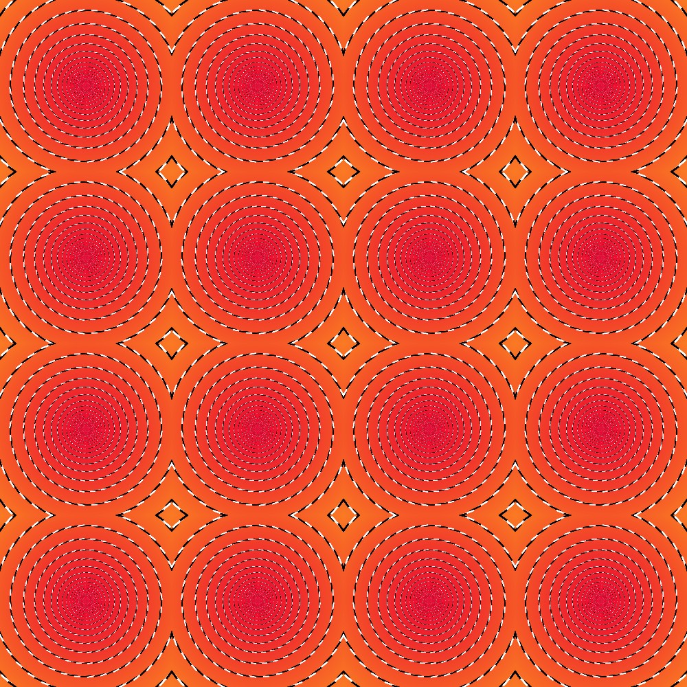
今回作成した錯視アート「アヒルのおしゃべり」です。

書籍では「同心円が渦巻きに見える。」と解説されています。そのように見えるような気がします。個人的には「薔薇攻撃」という作品の方がより「同心円が渦巻き」に見えます。
描き方のポイント
白色の棒と黒色の棒の並べ方
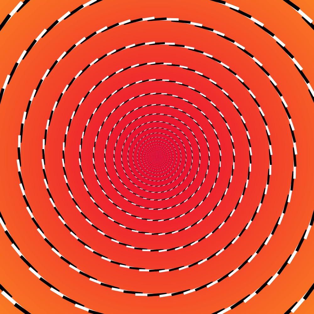
この作品「アヒルのおしゃべり」では以下の図形を4×4に並べて作成しています。

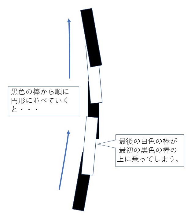
この図形は白色の棒と黒色の棒を交互の並べていくだけなので一見簡単そうに見えます。ただ、よく考えると、一本ずつ交互に並べていったときに最後に置く棒は最初に置いた棒の下にくぐらせる必要がありますが、単純に並べてしまうと、最後に置く棒は最初に置いた棒の上に乗ってしまいます。

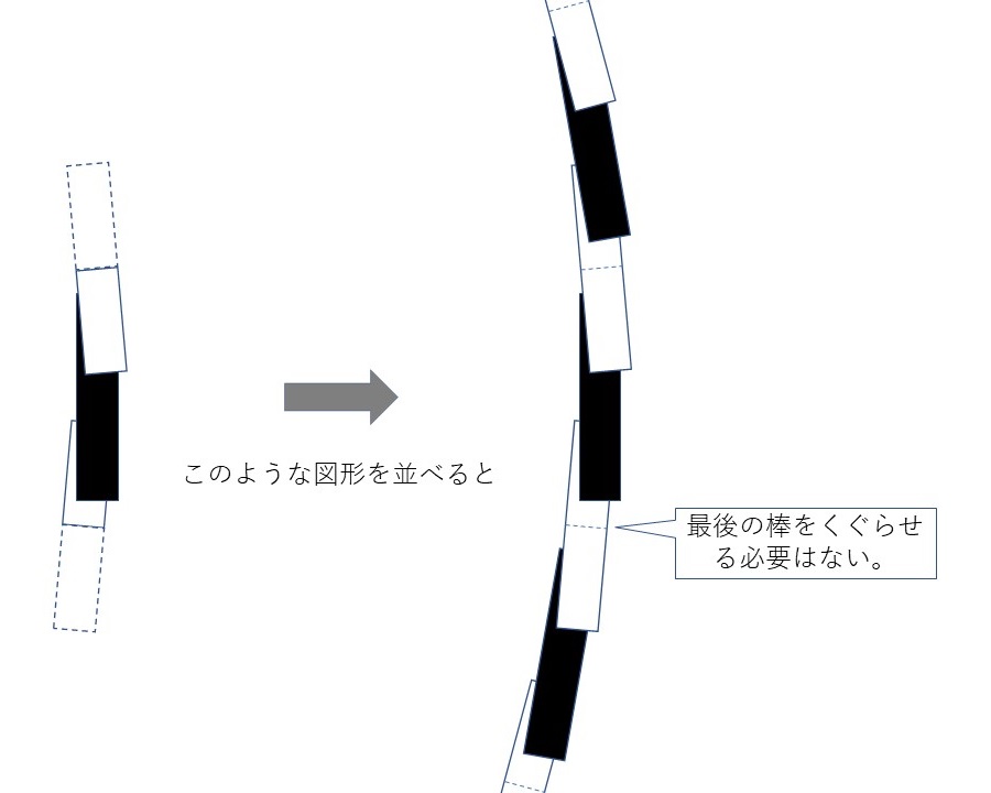
色の重ね合わせを工夫すれば、最後に置く棒が最初に置いた棒の下にくぐっているように描くことができると思いますが、背景色のことも考えると、すぐには思いつきませんでした。そこで今回は、並べていく図形を単純に白色の棒と黒色の棒にするのではなく、白色の棒を半分にしたもの2つと黒色の棒1つを組み合わせた図形として準備し、この図形を並べていくことで描いていくことにしました。

このようにすることで、最後に置く棒を最初に置いた棒の下にくぐらせるときの問題は回避することができます。
部分図形の作成
再度書きますが、この作品「アヒルのおしゃべり」では以下の図形を4×4に並べて作成しています。

この図形を素直に描くことは結構難しいと思います。何が難しいかというと、図形の境界で棒が切れていることです。棒が切れているように計算して描くことも不可能ではないと思いますが、かなり難しそうです。そこで、今回は次のように対処しました。
- まず、描画キャンパス一杯に上図のような図形を描いていきます。このとき、描画キャンパスからはみ出た部分は表示されませんので、棒が切れているように描くことができます。
- このキャンバスに描いた図形をいったん画像として取り込みます(PImageを利用する)。
- 取り込んだ画像のサイズを調整して(ここでは縦横4分の1のサイズにして)、キャンバスに並べて貼り付けていきます。
以上の手続きにより、作品「アヒルのおしゃべり」を再現することができました。
図形の並べ方
この作品の4×4に並んだ図形をよくよく見てみると、並べていく際に上下方向、左右方向に反転させていることが分かります。これに注意して図形を並べていきます。反転させて並べていく際の注意点は別記事「図形の移動、回転、反転」に記載していますので、参考にしてください。
プログラムコード
今回作成した錯視アート「アヒルのおしゃべり」のプログラムコードを載せておきます。
void setup() {
  size(1000, 1000);

  noStroke();
  translate(width/2, height/2);

  // 背景のグラデーションを描く
  float diameter = width * sqrt(2.0); // 一番外側の円の直径
  color col_out = color(#FA7923); // 円形のグラデーションの一番外側の色
  color col_in = color(#EA0231); // 円形のグラデーションの一番内側の色
  grdCircle(0.0, 0.0, diameter, col_out, col_in); // 円形のグラデーションを描く

  // 白色の棒と黒色の棒を円形に並べていく
  float x0 = width * sqrt(2.0); // 一番外側の円の半径
  float a0 = width / 4.0; // 一番外側の円と二番目に外側の円都の半径の差
  float ratio = 1.0 - a0 / x0; // 円の縮小比率
  int sticks_num = 36; // 黒色の棒と白色の棒のペアの数
  float theta = radians(360.0/sticks_num/2.0); // 棒1つ分の中心角の角
  for(int i=0; i<sticks_num; i++){
    drawSticks(x0, a0, ratio, theta);
    rotate(2.0 * theta);
  }

  // 描いた図形を一旦PImageに保存する
  PImage  img = createImage(width, height, RGB);
  loadPixels();
  for(int j=0; j<img.height; j++){
    for(int i=0; i<img.width; i++){
      img.set(i, j, pixels[j*width + i]);
    }
  }

  // 保存した図形を4分の1に縮小して並べていく
  for(int i=0; i<4; i++){
    for(int j=0; j<4; j++){
      resetMatrix();
      translate((i+(1-pow(-1,i))/2)*width/4, (j+(1-pow(-1,(j+1)/2))/2)*height/4);
      scale(pow(-1,i), pow(-1,(j+1)/2));
      image(img, 0.0, 0.0, width/4, height/4);
    }
  }
}

// 円形のグラデーションを描く関数
void grdCircle(
  float x, // 円の中心位置のx座標
  float y, // 円の中心位置のy座標
  float d, // 一番外側の円の直径
  color col_out, // 円形のグラデーションの一番外側の色
  color col_in   // 円形のグラデーションの一番内側の色
  ) {
  float c = 100;
  for (int i=0; i<c; i++) {
    color col = lerpColor(col_out, col_in, i/c); // 円の色
    float dd = lerp(d, 0.0, i/c); // 円の直径

    noStroke();
    fill(col);
    ellipse(x, y, dd, dd); // 円を描く
  }
}

// 白色の棒と黒色の棒を円形に並べていく関数
void drawSticks(
  float rs, // 一番外側の円の半径
  float segment_len_initial, // 一番外側の円と二番目に外側の円都の半径の差
  float ratio, // 縮小比率
  float theta // 棒1つ分の中心角の角度
){

  float x, y;
  float r;
  float segment_len;
  float shrink_ratio = 0.8; // x * sin よりも少し短くする
  float thickness = 0.1;
  float theta_slope = -radians(4.0); // 棒を少しだけ傾ける
  float x1, y1, x2, y2, x3, y3, x4, y4;
  float x1m, y1m, x2m, y2m, x3m, y3m, x4m, y4m;

  r = rs;
  segment_len = segment_len_initial;

  int i = 0;
  while(i<100){
    x = r * cos(theta);
    y = r * sin(theta);

    // 下部の白色の棒(半分)を描く
    x1 = - y * thickness;
    y1 = - y * shrink_ratio;
    x2 = - y * thickness;
    y2 = 0.0;
    x3 = y * thickness;
    y3 = 0.0;
    x4 = y * thickness;
    y4 = - y * shrink_ratio;
    x1m = x1 * cos(theta_slope+theta) - y1 * sin(theta_slope+theta);
    y1m = x1 * sin(theta_slope+theta) + y1 * cos(theta_slope+theta);
    x2m = x2 * cos(theta_slope+theta) - y2 * sin(theta_slope+theta);
    y2m = x2 * sin(theta_slope+theta) + y2 * cos(theta_slope+theta);
    x3m = x3 * cos(theta_slope+theta) - y3 * sin(theta_slope+theta);
    y3m = x3 * sin(theta_slope+theta) + y3 * cos(theta_slope+theta);
    x4m = x4 * cos(theta_slope+theta) - y4 * sin(theta_slope+theta);
    y4m = x4 * sin(theta_slope+theta) + y4 * cos(theta_slope+theta);

    noStroke();
//    y1 = x * sin(theta);
    fill(255,255,255);
    pushMatrix();
    beginShape();
    vertex(x+x1m,y+y1m);
    vertex(x+x2m,y+y2m);
    vertex(x+x3m,y+y3m);
    vertex(x+x4m,y+y4m);
    endShape(CLOSE);
    popMatrix();

    // 次に、黒色の棒を一部重ねて描く
    x1 = - y * thickness;
    y1 = - y * shrink_ratio;
    x2 = - y * thickness;
    y2 = y * shrink_ratio;
    x3 = y * thickness;
    y3 = y * shrink_ratio;
    x4 = y * thickness;
    y4 = - y * shrink_ratio;
    x1m = x1 * cos(theta_slope) - y1 * sin(theta_slope);
    y1m = x1 * sin(theta_slope) + y1 * cos(theta_slope);
    x2m = x2 * cos(theta_slope) - y2 * sin(theta_slope);
    y2m = x2 * sin(theta_slope) + y2 * cos(theta_slope);
    x3m = x3 * cos(theta_slope) - y3 * sin(theta_slope);
    y3m = x3 * sin(theta_slope) + y3 * cos(theta_slope);
    x4m = x4 * cos(theta_slope) - y4 * sin(theta_slope);
    y4m = x4 * sin(theta_slope) + y4 * cos(theta_slope);

    noStroke();
//    y1 = x * sin(theta);
    fill(0,0,0);
    pushMatrix();
    beginShape();
    vertex(x+x1m,y1m);
    vertex(x+x2m,y2m);
    vertex(x+x3m,y3m);
    vertex(x+x4m,y4m);
    endShape(CLOSE);
    popMatrix();

    // 上部の白色の棒(半分)を描く
    x1 = - y * thickness;
    y1 = 0.0;
    x2 = - y * thickness;
    y2 = y * shrink_ratio;
    x3 = y * thickness;
    y3 = y * shrink_ratio;
    x4 = y * thickness;
    y4 = 0.0;
    x1m = x1 * cos(theta_slope-theta) - y1 * sin(theta_slope-theta);
    y1m = x1 * sin(theta_slope-theta) + y1 * cos(theta_slope-theta);
    x2m = x2 * cos(theta_slope-theta) - y2 * sin(theta_slope-theta);
    y2m = x2 * sin(theta_slope-theta) + y2 * cos(theta_slope-theta);
    x3m = x3 * cos(theta_slope-theta) - y3 * sin(theta_slope-theta);
    y3m = x3 * sin(theta_slope-theta) + y3 * cos(theta_slope-theta);
    x4m = x4 * cos(theta_slope-theta) - y4 * sin(theta_slope-theta);
    y4m = x4 * sin(theta_slope-theta) + y4 * cos(theta_slope-theta);

    noStroke();
    fill(255,255,255);
    pushMatrix();
    beginShape();
    vertex(x+x1m,-y+y1m);
    vertex(x+x2m,-y+y2m);
    vertex(x+x3m,-y+y3m);
    vertex(x+x4m,-y+y4m);
    endShape(CLOSE);
    popMatrix();

    // 比率を更新
    r = r - segment_len;
    segment_len = segment_len * ratio;
    i++;
  }
}